НОМТ tower: 3D model and walkthrough, checked against the drawings
The model was built from measurements extracted from the architect's drawing set and cross-checked against the Revit DWG. Every window and door position, width, sill and head traces back to a sheet, and every check below ran automatically and passed.
Walkthrough
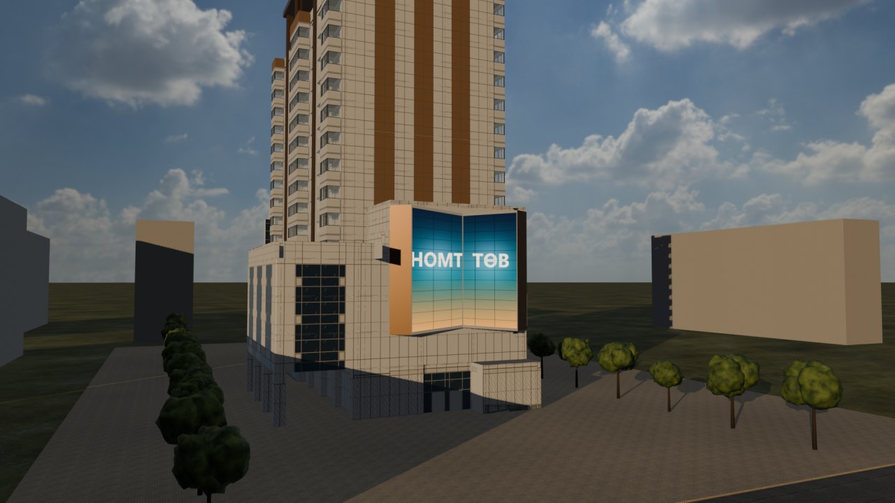
2:31 · 16:9 · 1080pFinal render. Native 1920×1080, 16 samples, denoised (a compressed copy plays here; the full-quality
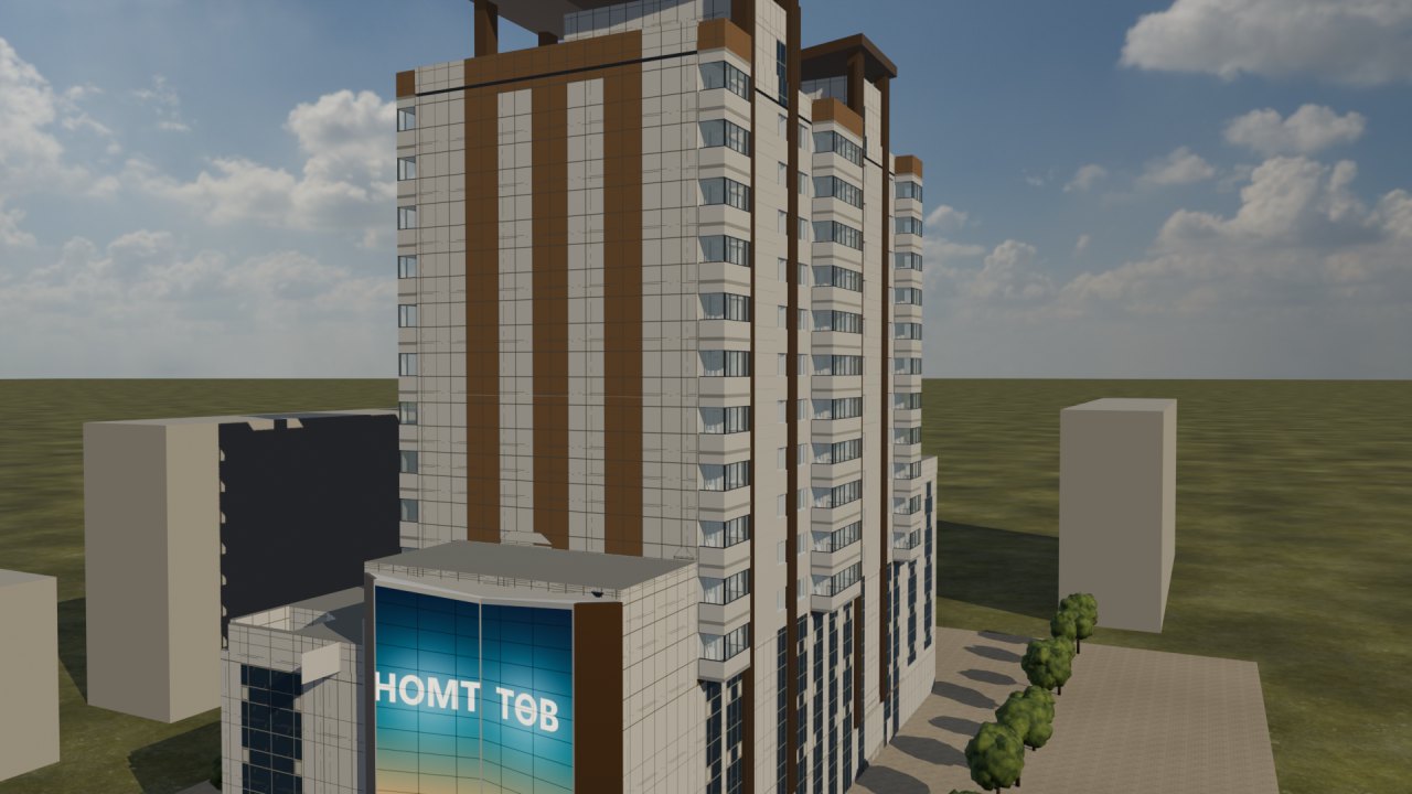
file is deliverables/video/nomt-walkthrough.mp4). It shows all four sides, the south wing's "open book" LED screen,
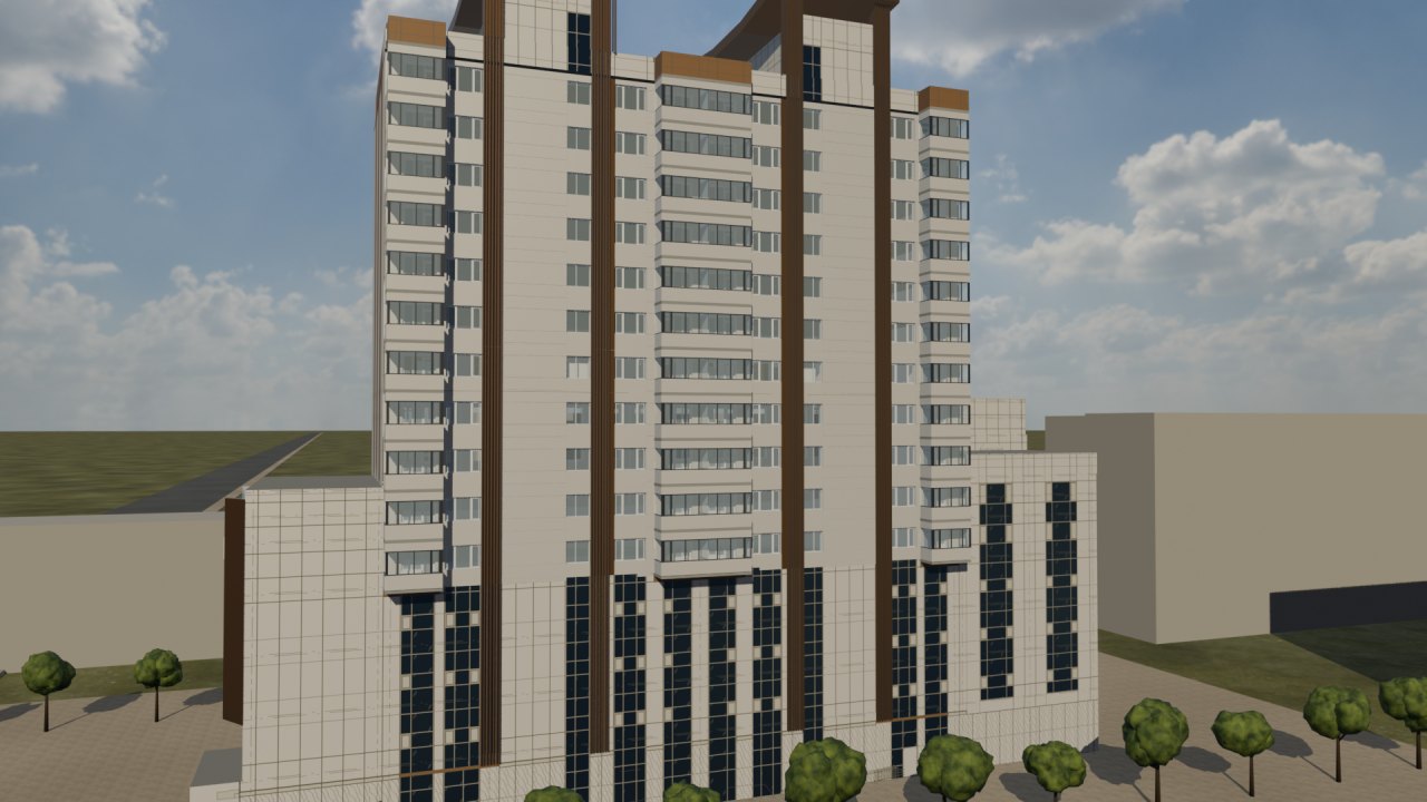
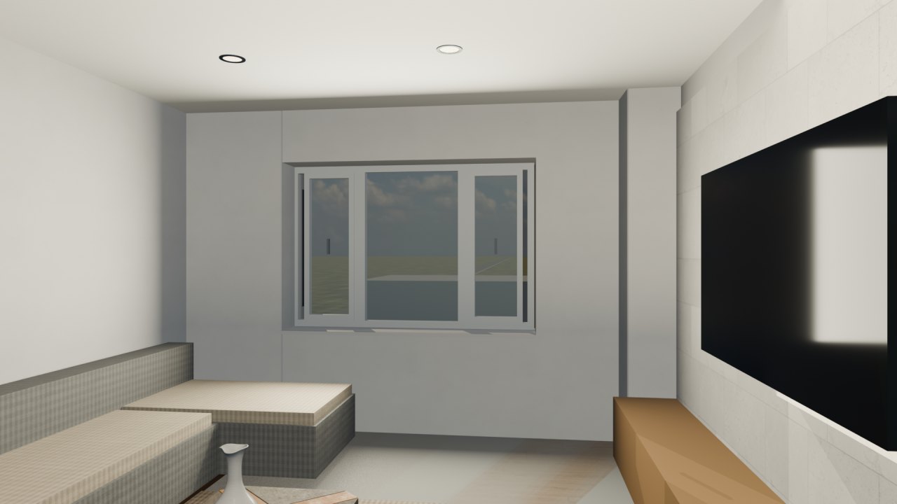
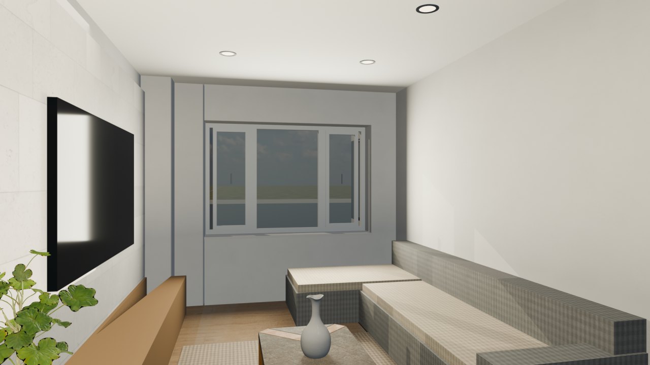
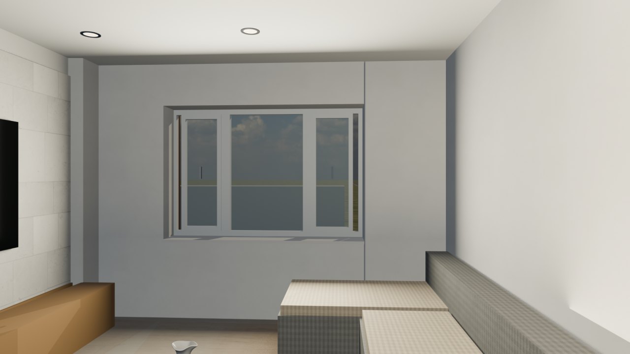
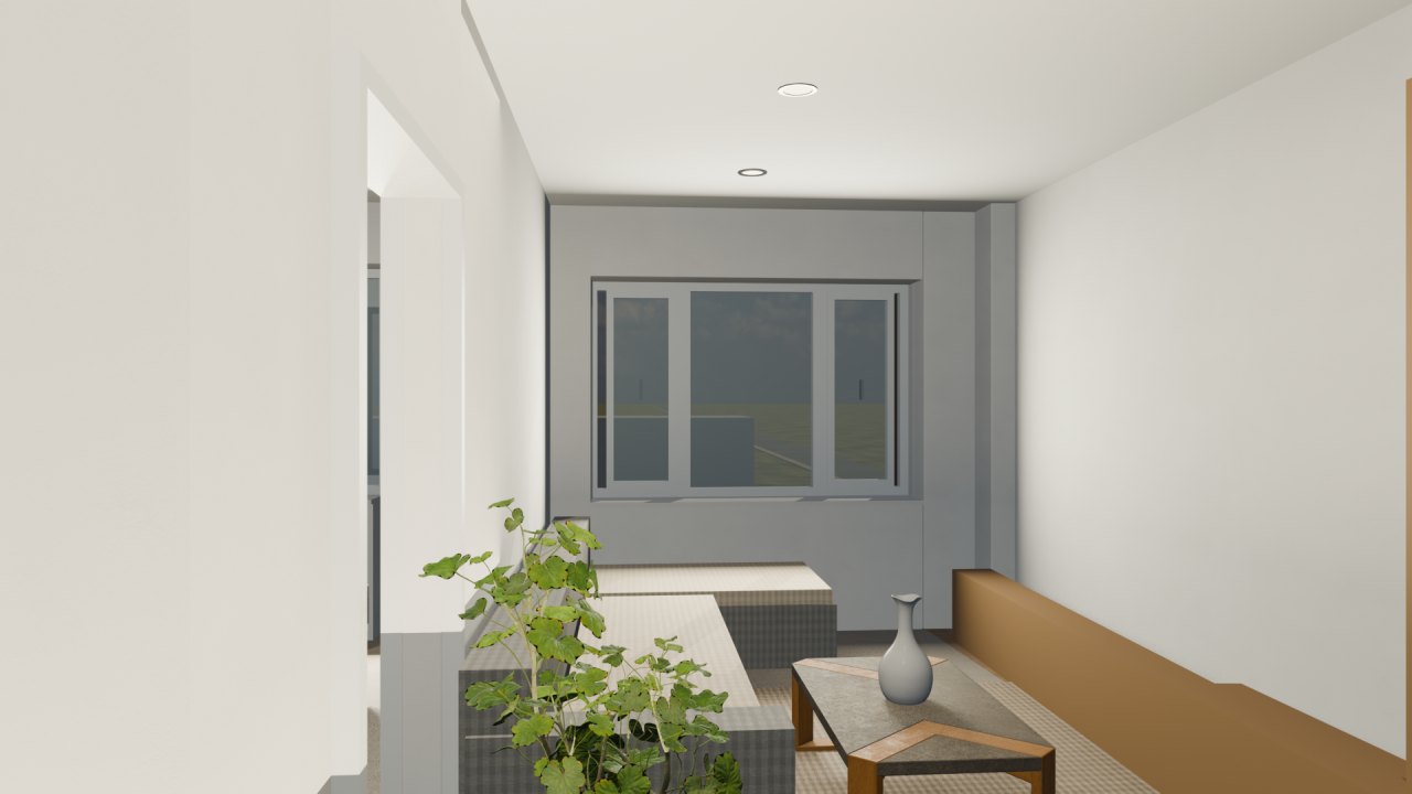
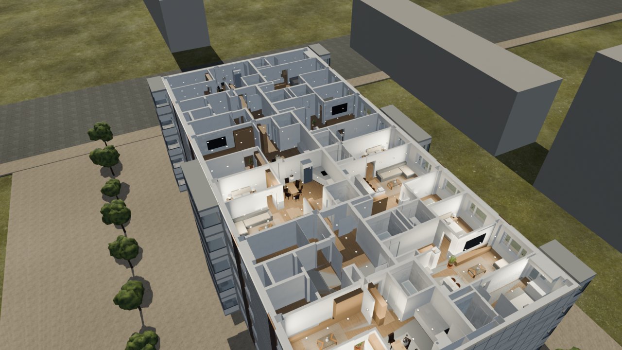
four flats (A, B, C, D) and the typical-floor cutaway.
What was checked
all passingCamera paths are planned through the flats' free floor space and sampled every 5 cm against walls, furniture and open door leaves; every frame's view is also tested so the camera never stares into a wall.
Model over the original sheets
p11 · p16 · p17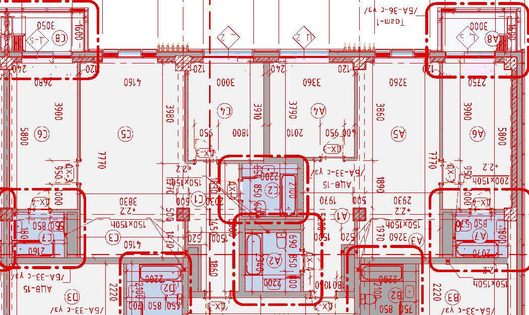
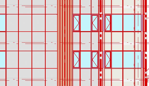
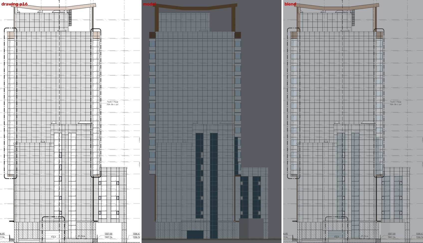
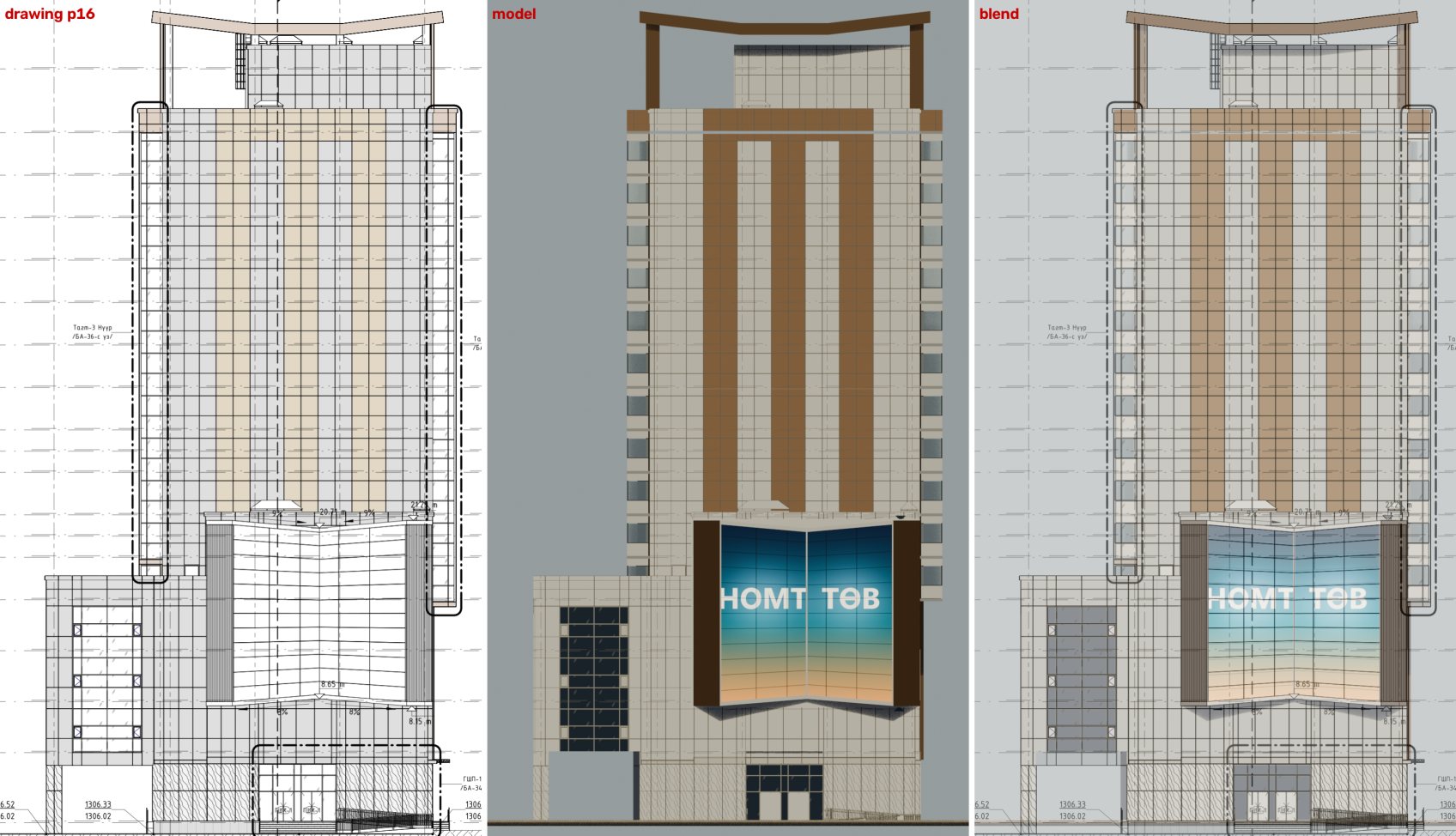
Full-size overlays: plan_overlay.jpg (whole floor) and elev_overlay_E.jpg (east face, floors 5–15).
Windows and doors per flat
floors 8–15 · p19 schedule| Type | m² | Rooms | Faces | Balcony | Balcony door-window | Living window | Bedroom window | Doors |
|---|---|---|---|---|---|---|---|---|
| A | 74.32 | 3 | West | Тагт-1 | Ц-3 · head 2.40 | 3-part · 0.87–2.34 | Ц-2 · 2000×1400 | 1 + 2 + 2 |
| B | 59.54 | 2 | East | Тагт-1 | Ц-3 · head 2.40 | 3-part · 0.87–2.34 | — | 1 + 1 + 1 |
| C | 79.29 | 3 | West | Тагт-2 | Ц-4 · head 2.30 | 3-part · 0.87–2.34 | Ц-2 · 2000×1400 | 1 + 2 + 2 |
| D | 68.71 | 2 | East | Тагт-2 | Ц-4 · head 2.30 | 3-part · 0.87–2.34 | — | 1 + 1 + 1 |
| E | 74.55 | 3 | West | Тагт-1 | Ц-3 · head 2.40 | 3-part · 0.87–2.34 | Ц-2 · 2000×1400 | 1 + 2 + 2 |
| F | 60.10 | 2 | East | Тагт-1 | Ц-3 · head 2.40 | 3-part · 0.87–2.34 | — | 1 + 1 + 1 |
| G | 79.29 | 3 | West | Тагт-2 | Ц-4 · head 2.30 | 3-part · 0.87–2.34 | Ц-2 · 2000×1400 | 1 + 2 + 2 |
| H | 68.70 | 2 | East | Тагт-2 | Ц-4 · head 2.30 | 3-part · 0.87–2.34 | — | 1 + 1 + 1 |
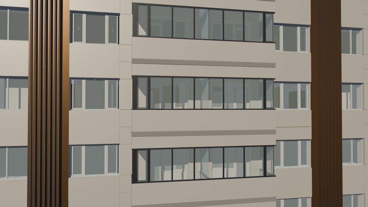
Doors are entrance ДХ-2 (1050) + bedroom ДХ-3 (950) + WC ДХ-4 (850). Living windows: casement | fixed | casement, heights in metres above the floor. Balconies are enclosed, 3.0 × 1.6 m clear, glazed 0.89–2.31 m over a parapet. Floor 15's living windows are drawn 0.135 m taller; the model follows that.
To confirm with the architect
found by the checks- Ц-2 height. The p19 table says 1500; Ц-2's own detail (20 + 1350 + 30) and elevation p18 say 1400. Modelled 1400. p19 · p18
- “Ц-3” means two things. p18 tags the living-room window vents Ц-3; p19's Ц-3 is the balcony door-window. Each drawing's geometry was followed; the living-room window is not in the schedule. p18 · p19
- Flat G balcony opening. The p11 dimension string gives 1980 + 1220; the DWG and the p19 schedule give 2000, like the other seven. Modelled 2000. p11 · DWG · p19
- Balcony glazing Ц-5 / Ц-6 is tagged on the plans and p33 but missing from the p19 schedule. p11 · p33 · p19
- Bronze colour. CMYK 37/52/19/0 on the sheets converts to mauve, while the drawing fill reads bronze-beige. Rendered as bronze. p16–p18 legend
- "Open book" outline. Plans p5–p7 draw a second, thin outline 0.5 m outside the screen's thick outline; the east elevation p17 and the 1250 mm dimension match the thick one. Modelled on the thick outline. p5–p7 · p17
- Choices made for the visualisation (not in the drawings): bedding, lamps and cushions (the beds and nightstands themselves are from the DWG); WC doors shown closed; 11 Revit furniture pieces (10 wardrobes, 1 kitchen unit) moved 4–10 cm out of walls they overlapped; balcony frame colour, surrounding blocks and trees are placeholders; the LED screen shows a placeholder "НОМТ ТӨВ". logged in scene_spec.json
3D model
glTF · BlenderDrag to orbit the furnished typical floor (floors 8–15 layout, all 8 flats). Files are in the project folder:
deliverables/3d/nomt.blendFull scene: tower floors 5–15 as instances, floor 9 furnished, podium, crown, site, lightsdeliverables/3d/nomt-building.glbWhole building + site, Draco-compressed (5.2 MB)deliverables/3d/nomt-typical-floor.glbFurnished typical floor, Draco (0.5 MB); uncompressed copy used heredeliverables/video/Walkthrough filmnomt-walkthrough.mp4(1080p) andnomt-walkthrough-4k.mp4(AI 4K upscale)
How it was built
tools/- Plan chains, door cut-outs and tags on p10/p11 give every opening; elevations p16–p18 give frames, sills and heads (
extract_openings.py). - The Revit DWG gives each door and window as a named element; a fitted transform compares both sources (
extract_dxf.py,verify_sources.py). - Walls, windows, doors, balconies, fins and the architect's furniture become a checked scene spec (
scene_spec.py,furniture_spec.py,massing_spec.py). - Blender builds and renders it; orthographic renders are overlaid on the sheets (
blender_build.py,overlay_check.py). - Camera paths are planned and checked through free space; frames render in EEVEE and are cut with Mongolian titles (
shots.py,render_shots.py,edit_video.py).
Apartment types A–H: per-type 3D files, checks and 4K renders →
Measurement audit: every plan dimension vs the model →
The film itself is the Blender render. Higgsfield was used only to upscale it to 4K (Topaz) — the frames still come from the model, so windows and doors cannot drift. A photoreal AI restyle of the approach was tested and kept out of the film: trees popped in and the surrounding city was invented.